While experimenting with my G8689 CNC conversion, I allowed a grounded wire to come into contact with terminal 7 of the G8689 motor controller. The fuse was blown and the controller was damaged. LMS sells these as their part number 1211. Since LMS was out of stock I went ahead and fixed mine. LMS has some good top level trouble shooting information on their site for these controllers. Look there first and make the tests they describe. If you need to dig deeper and have some test equipment and technician skills use the info I have posted here.
Be extremely careful connecting any line supplied test equipment to the controller. The controller is not isolated from the line and much of the circuit is HOT. A line isolation transformer should be used. Battery powered test equipment is fine of course.
Keep one hand in your pocket (if you have two hands) while making measurements. There
may be a clear coating on the non-component side of the controller PCBs which
makes probing difficult. I recommend probing from the component side.
FC350BJ_SCH - Main board schematic.
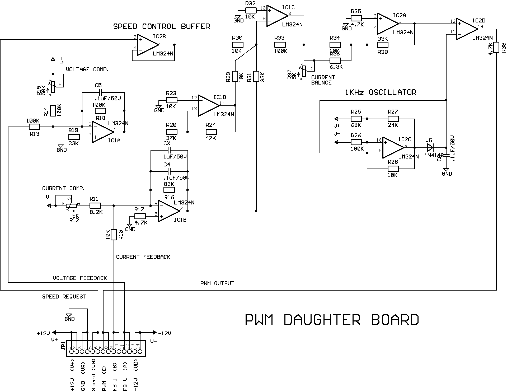
FC350BJ_PWM_SCH - PWM daughter board
schematic.
The following files are rough layouts of the components and reference designators. The reference designators may not be accurate since I didn't remove the components to read them and many were difficult or impossible to read.
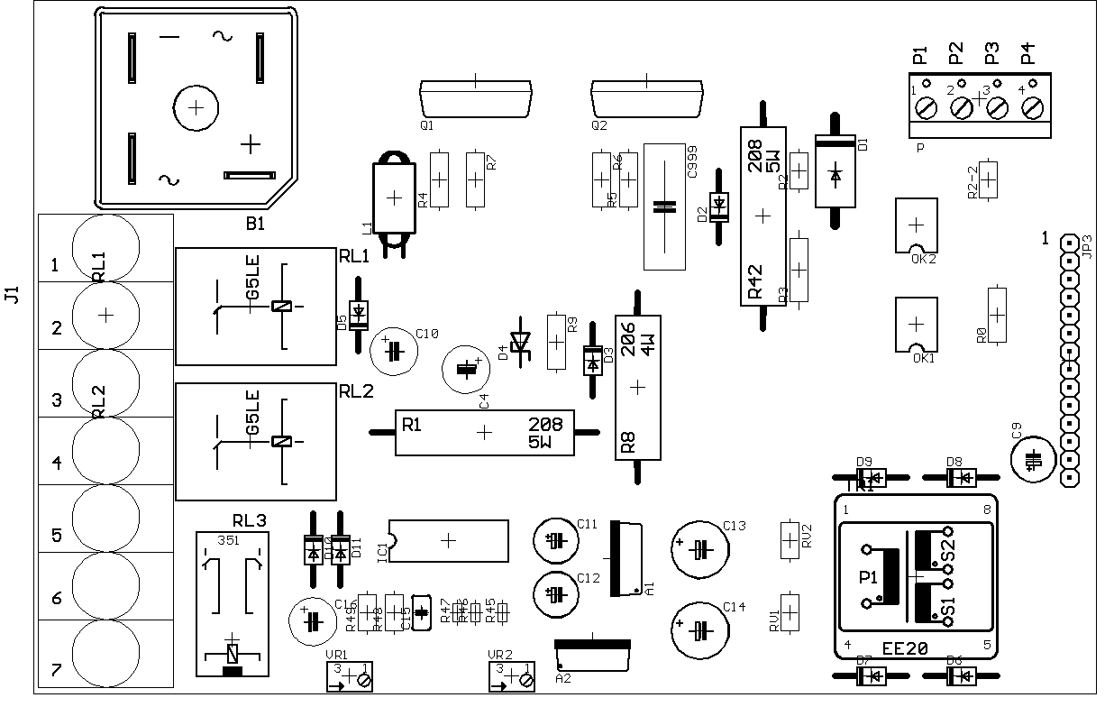
FC350BJ_BRD - Main board layout.
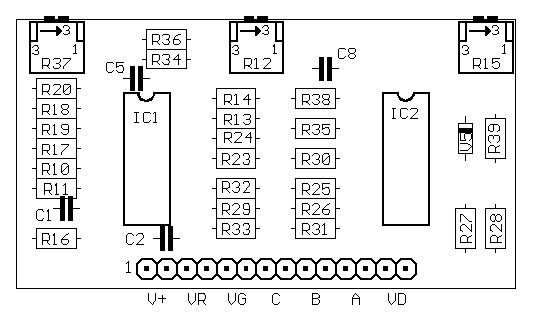
FC350BJ_PWM_BRD - PWM daughter board
layout.
Note that there are two different grounds on the schematic: PE (power earth) and GND (signal ground). The anode (non-stripe end) of D4 is a good place to connect for PE. The tab of A2, the +12V regulator is a good place to connect for GND. If you have a battery powered DVM do a quick check of + and - 15V and + and - 12V supply to signal ground. If these are good check the PWM output between signal ground and OK1 pin 1 (an optical isolator with 6 total pins, pin one has the dot next to it. You should be able to swing the value between -.6V (low speed) and +.6V (hi speed) while while changing the speed control pot. If you have an isolated scope you should see a 1 KHz 1.2Vpp PWM waveform here. If you don't get a changing signal at the PWM output and the inputs to the PWM board seem to match the table, you'll need to trouble shoot PWM board. The best way to trouble shoot the PWM board is to remove it from the main board by sacrificing the 14 position right angle.025" square header posts (.1" pitch) with which it is attached. These header posts are available inexpensively from Digikey. Once the PWM board is removed, just connect it to a +-12V lab supply and three pots for the Speed, FB I and FB V inputs. With this setup it should be easy to trouble shoot. When the PWM board is disconnected the PWM output should be a 1 KHz 20Vpp PWM waveform. The following table gives some nominal DVM readings with both boards connected.
|
Signal Name |
Handy Probe Location |
Lo Speed |
Hi Speed |
| +12V (V+) | A2, output | +12V | +12V |
|
GND (VR) |
Mounting Tab A2 | N/A | N/A |
|
Speed (VG) |
Terminal P2 | 0V | +12V |
| PWM (C) | OK 1, pin 1 | -.6V | +.6V |
| FB I (B) | R1 end near RL2 | +12V (decreases with motor load) | +11.5V (decreases with motor load) |
| FB V (A) | R2 end near R3 | 11.2V | 6.7V |
| -12V (VD) | A1, output | -12V | -12V |
Good luck, and if you get stuck e-mail me and I'll try and help.